| Dimension | Processor Model | Input Voltage Range | Output Voltage Range | Peak Current |
|---|---|---|---|---|
| Length: 140mm, Width: 82mm, Height: 40mm | RK3588S | 24V~50V | 24V~50V | 30A |
| FDCAN Baud Rate | Number of CAN/FDCAN Channels | Function Expansion Interface | IMU | Development Environment |
|---|---|---|---|---|
| 5Mbps | 7Channels | GH_1.25_3p/4p/5p | YIS130 | ROS1 |
| Voice Interface Expansion | 4G Module Expansion |
|---|---|
| Supported | Supported |
• Model Number
• Function positioning (Introduction)

Length: 140mm, Width: 82mm, Height: 40mm (with housing)
Length: 134.8mm, Width: 77.3mm, Height: 21.3mm (without housing)
(1) Input Voltage Range: 24V - 50V
(2) Output Voltage Range: 24V - 50V
(3) FDCAN Baud Rate: 5Mbps
(4) 7 CAN/FDCAN Channels
(5) Function Expansion Interfaces: All are 25_3p/4p/5p
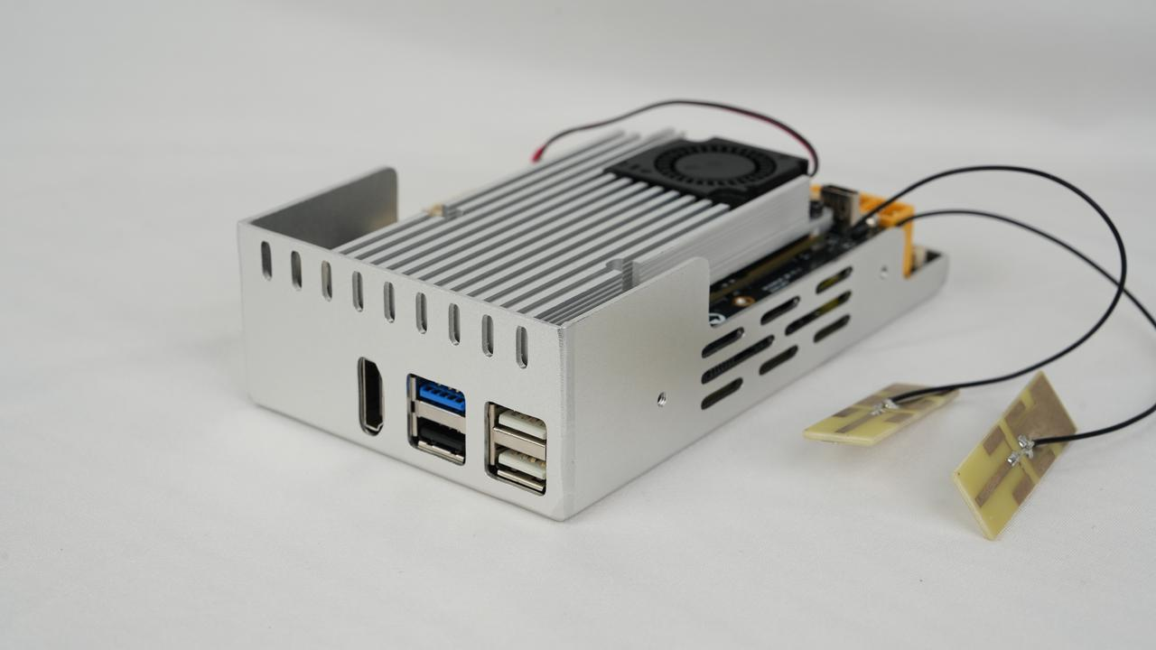
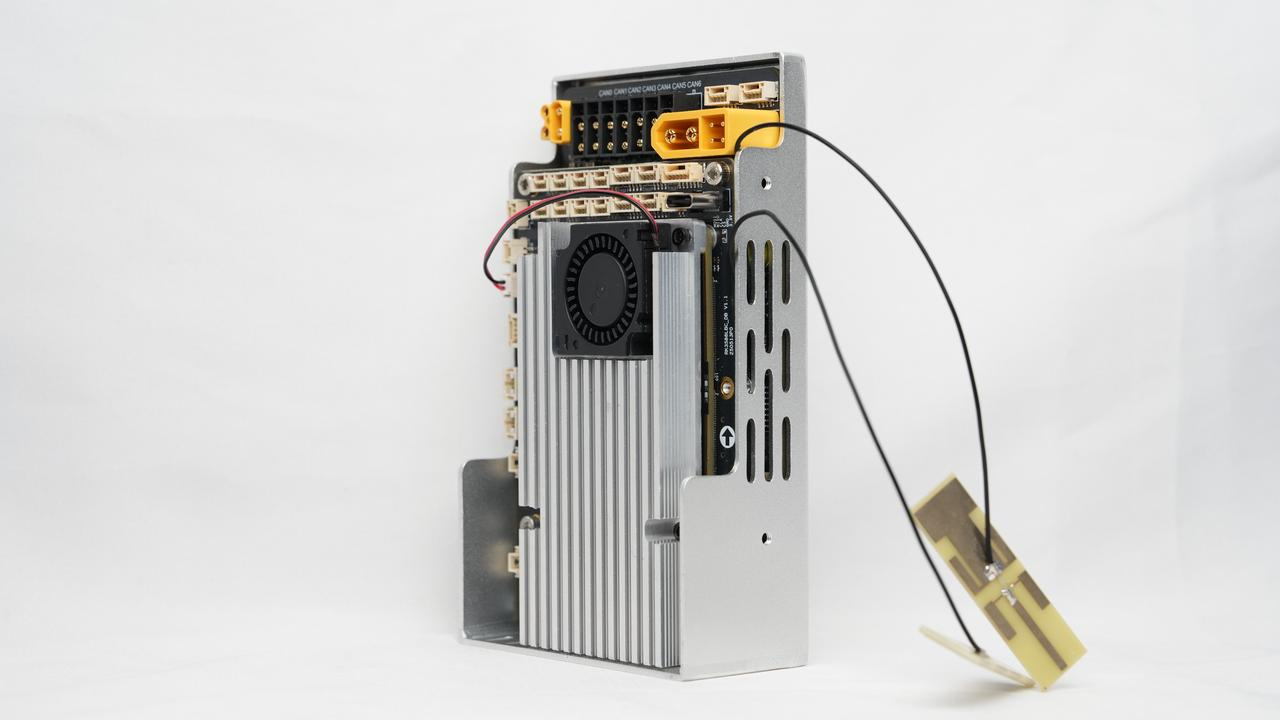
The LubanCat Main Control Box consists of three parts: the RK3588 Core Board, the RK3588 Base Board, and the Power Board plus IMU.
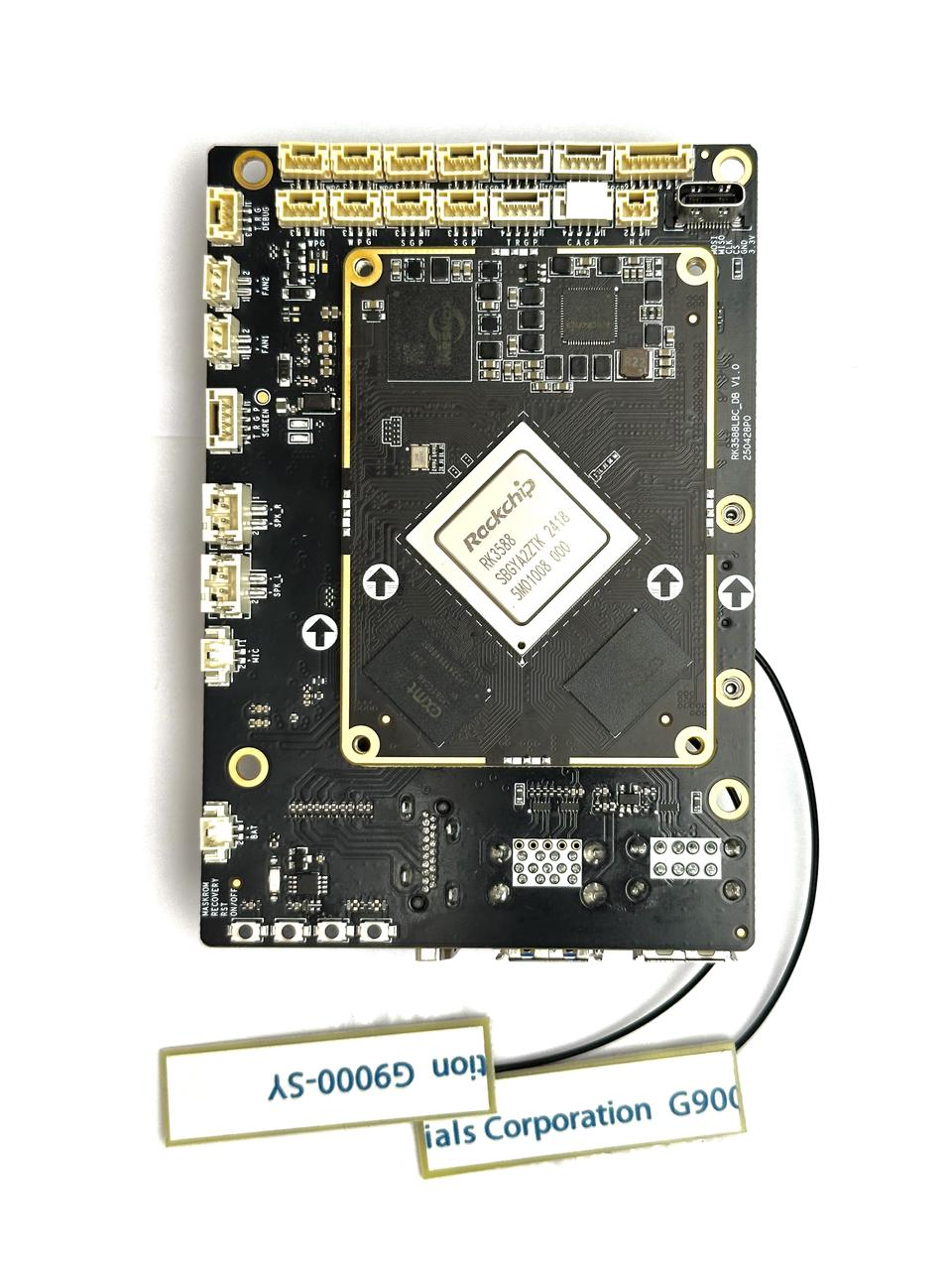
(1)Robot Main Control Box - RK3588 Core Board
The core board is equipped with an eight-core CPU processor-RK3588 with four-core A76+ and four-core A55. It has a powerful GPU and a built-in NPU with 6T computing power. In addition, the core board is also equipped with large-capacity eMMC and DDR chips, and the maximum external peripherals of the chip are realized through BTB pins.
(2)Robot Main Control Box - RK3588 Base Board
It features a separate core board design, providing abundant connection options and expansion interfaces. Such as multiple USB ports (USB 2.0 and USB 3.0), an HDMI output interface, a TF card slot, a Mini-PCIe socket supporting 4G or WiFi, as well as a Type-C interface, a Debug serial port, and audio input/output ports. It supports a variety of peripheral connections and debugging functions, making it an ideal choice for developers engaged in hardware design and software development.
(3)Robot Main Control Box - 7-Channel CAN - Power Board
The 7-Channel CAN - Power Board is specifically designed for high-efficiency power and communication applications. It receives 48V input through an XT60 (2+4) power interface and provides 2 Debug serial ports for convenient debugging and development. The board includes 7 XT30 (2+2) interfaces for power output, etc., and supports 12V voltage output to supply power to the carrier board. In addition, the board is also integrated with one IMU module and one debugging interface, ensuring diversified function expansion and a stable power supply system.
• Interface Overview Diagram
• Definition of Each Interface (Pinout Diagram, Functional Description)
• Example Connection Topology (Connecting to Motors, Power Supply, Computers, etc.)
• Installation Method or Mounting Hole Diagram
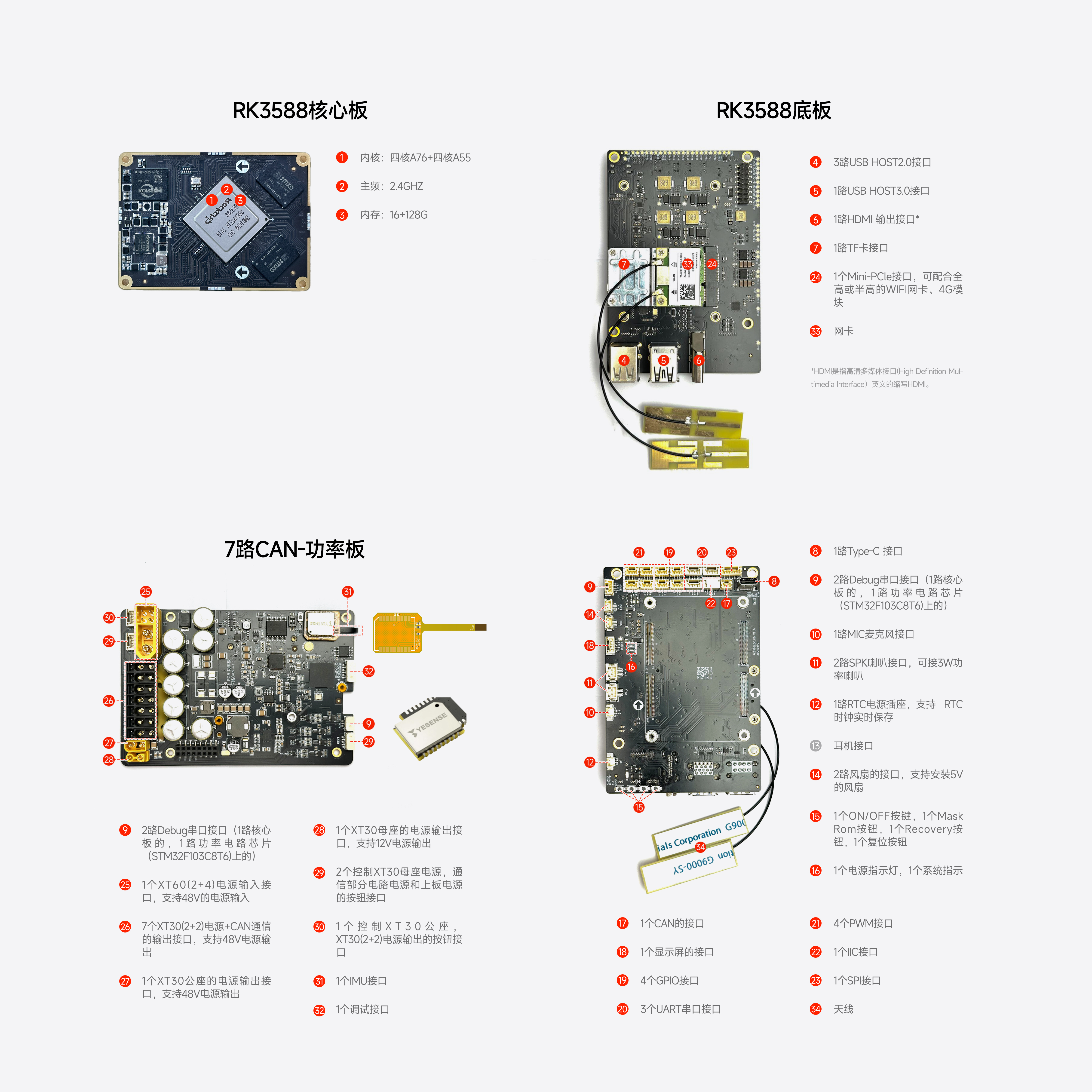
| 1. CPU Core: 4-core A76 + 4-core A55
2. Main Frequency: 2.4GHz 3. Memory: 16GB + 128GB 4. 3 USB HOST 2.0 Interfaces 5. 1 USB HOST 3.0 Interface 6. 1 HDMI Output Interface 7. 1 TF Card Interface 8. 1 Type-C Interface 9. 2 Debug Serial Interfaces (1 on the core board, 1 on the power circuit chip (STM32F103C8T6)) 10. 1 MIC (Microphone) Interface
|
11. 2 SPK Speaker Interfaces, compatible with 3W power speakers
12. 1 RTC Power Socket, supporting real-time retention of the RTC clock 13. Headphone Interface 14. 2 Fan Interfaces, supporting the installation of 5V fans 15. 1 ON/OFF Button, 1 Mask ROM Button, 1 Recovery Button, 1 Reset Button 16. 1 Power Indicator Light, 1 System Indicator Light 17. 1 CAN Interface 18. 1 Display Screen Interface 19. 4 GPIO Interfaces 20. 3 UART Serial Interfaces
|
21. 4 PWM Interfaces
22. 1 IIC Interface 23. 1 SPI Interface 24. 1 Mini-PCle Interface, compatible with full-height or half-height WiFi network cards and 4G modules 25. 1 XT60(2+4) Power Input Interface, supporting 48V power input 26. 7 XT30(2+2) Output Interfaces for Power + CAN Communication, supporting 48V power output 27. 1 XT30 Male Power Output Interface, supporting 48V power output 28. 1 XT30 Female Power Output Interface, supporting 12V power output 29. 2 Button Interfaces for controlling the power of XT30 female sockets, the power of communication circuit sections, and the power of the upper board 30. 1 Button Interface for controlling the power output of XT30 male sockets and XT30 (2+2) interfaces 31. 1 IMU Interface 32. 1 Debug Interface 33. Network Card 34. Antenna |
• The 2 control buttons are a large button (with cable) and a small button (with cable) respectively.
• XT30 (20cm - Male-to-Female), XT30 (20cm - Female-to-Female)
• 5 XT30 (2+2) wires
• 1 Zero Data Cable (for programming)
• Heat Sink (Aluminum Block & Fan)
• Recommended System Environment (e.g., 04)
It is recommended to use the Ubuntu system (Ubuntu 20.04 system) that comes pre-installed with the product, along with the configured ROS environment (Noetic).
• Install Drivers/Dependencies
If using the official SDK requires configuring the ROS environment (Noetic), a serial communication driver must be installed, and the commands are as follows:
sudo apt-get install libserialport0 libserialport-dev
• Development Environment Used
Such as ROS1 (Noetic), CAN Debugging Tools, Serial Port Assistants, etc.